
Augmented Reality Research
Object persistence
Introduction
In marker-based AR systems, once a marker is out of view, objects placed in relation to it disappear. This is because marker based systems only have recognised markers to refer to when placing objects - they have no knowledge of the rest of the scene. This is an issue with large scale objects because the marker can move out of view quite quickly, as small camera movements, especially in pitch and yaw, are magnified in effect over the kind of distances we are working with.
In more sophisticated AR systems that detect real-world features (e.g. flat surfaces), a model of the scene is built so that objects can be placed with reference to this model, rather in reference to a marker. For mobile devices, feedback from onboard sensors, such as gyroscopes and accelerometers, are used to track movements of the camera to update the accuracy of the model. This allows the user to pan around a scene smoothly, and the object will persist if it is no longer in frame.
In-browser AR systems cannot use these techniques fully: surface detection is not available and calculating the predicted position of a marker once it goes out of view, based on feedback from onboard sensors is not possible currently.
Using Multiple Markers
In-browser AR systems can recognise multiple markers, and we are investigating whether this ability can be used to tackle object persistence . The theory is as follows:
- We use multiple markers to create a model of the scene with the assumption that at least one marker is in view at any one time
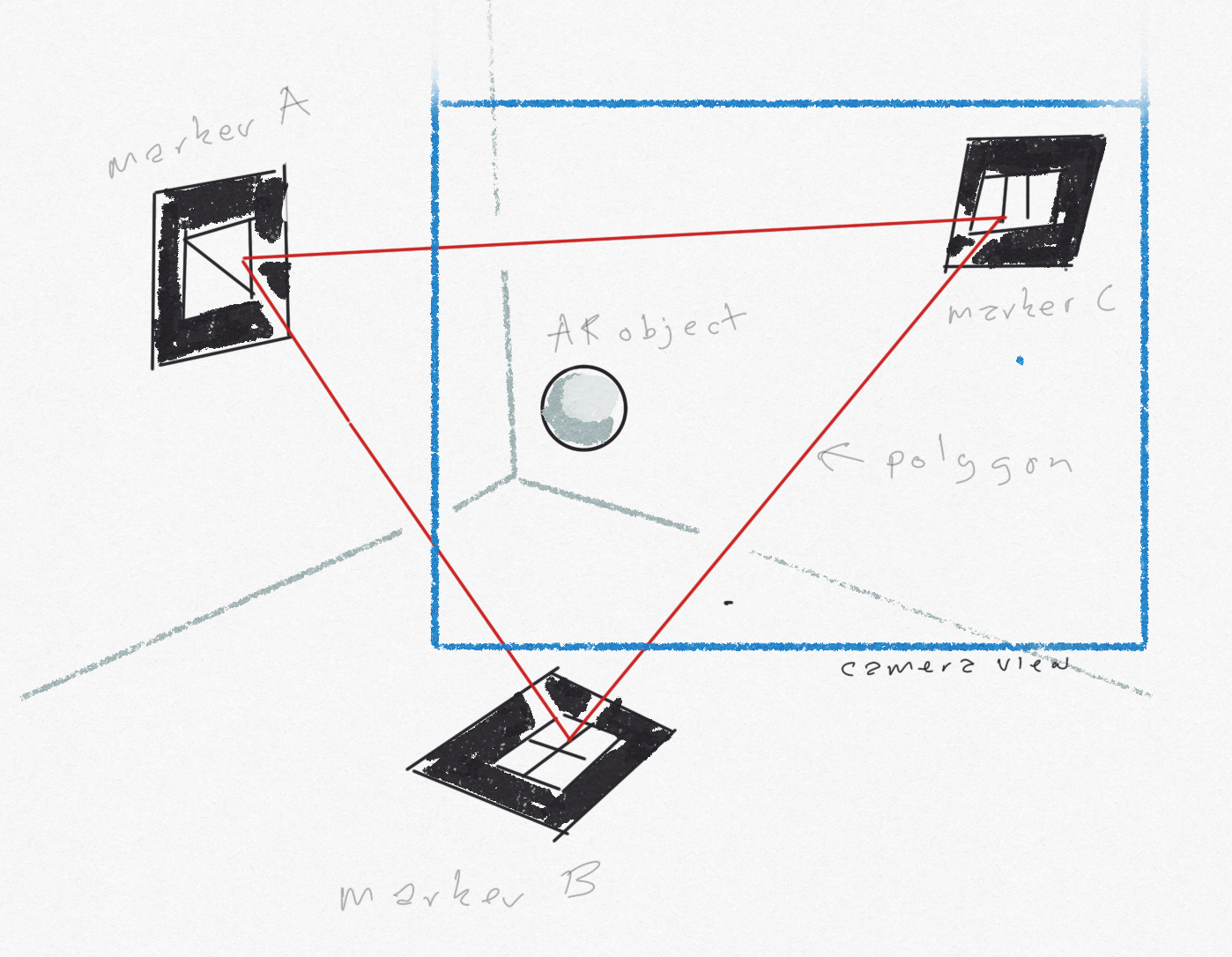
- The orientation and positions of the markers relative to each other are used to create a reference polygon*** within the scene, where each marker is a vertex of the polygon.
- Given that at least one vertex of the polygon is in view at any one time we can use it as stable reference for placed objects
- Initially we will draw this reference polygon in scene: linking each marker with a line (each vertex with an edge)
- We can then place AR objects in relation to this polygon, thereby creating limited object persistence
A brief digression on the (simplified) mathematics of browser-based AR
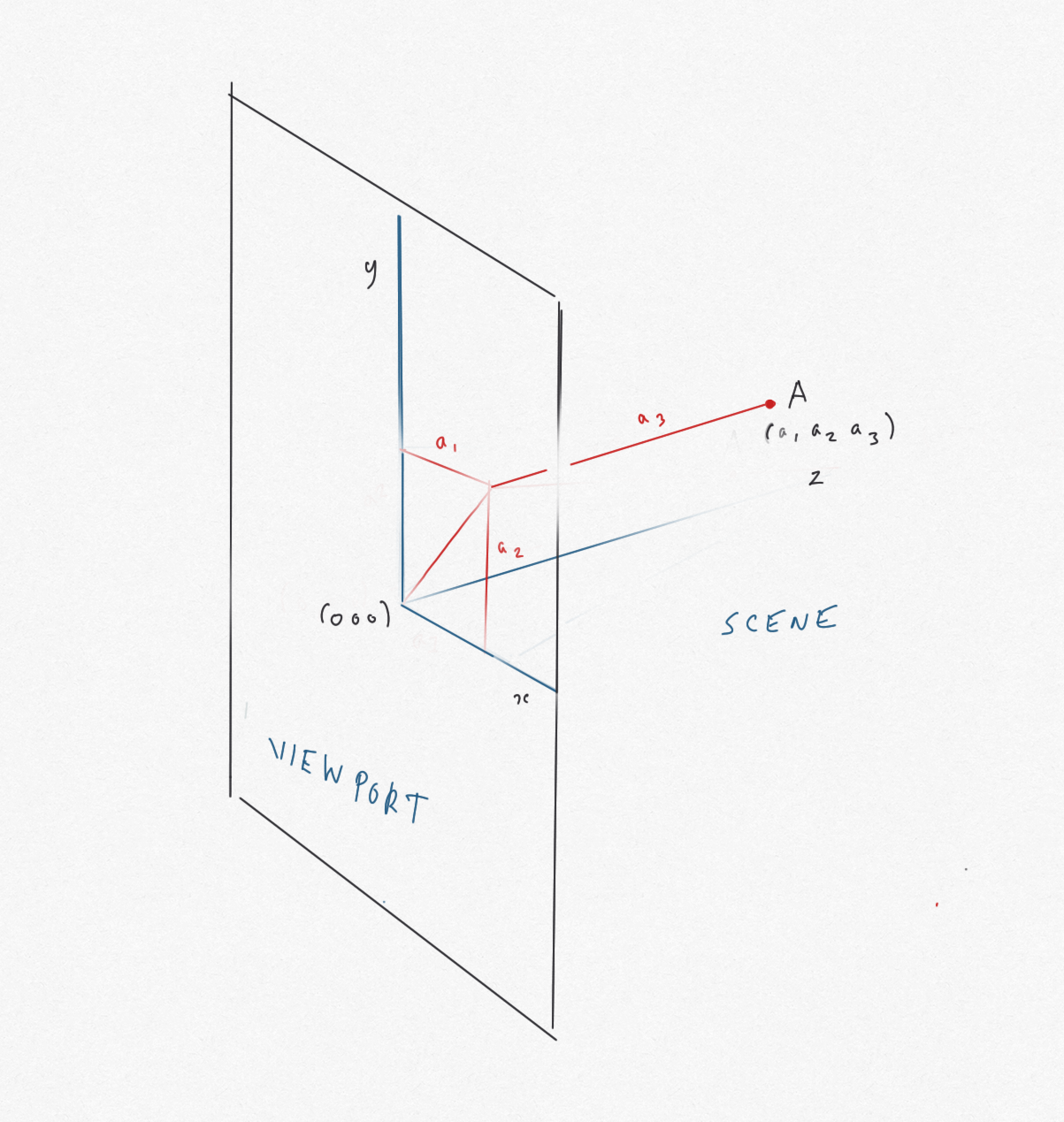
AR uses a three co-ordinate system with the camera at the origin (0,0,0) and axes of x, y and z. The viewport (i.e. the device screen) is represented as a rectangle centred on the origin, with z = 0, extending parallel to the x and the y axes the length and breadth of the screen.
For an object at point (x, y, z), y measures the height above the origin, x the distance from the origin across the viewport, and z measures the perpendicular distance to the object from the viewport into the scene
For the purposes of this digression, we will discuss two objects and the line between them, rather than a reference polygon with three vertices.
If you have markers at point A and point B in the AR scene, these are represented by the vectors (a1, a3, a3) and (b1, b2, b3) respectively.
For example, to get to A from the origin, you go distance a1 along the x-axis, distance a2 parallel to the y-axis, and distance a3 into the scene parallel to the z-axis
The distance dA from the origin (i.e. the camera) to the point A is found using the Pythagoras theorem:
dA = square root (a12 + a22 + a32 )
Similarly, dB = square root (b12 + b22 + b32 )
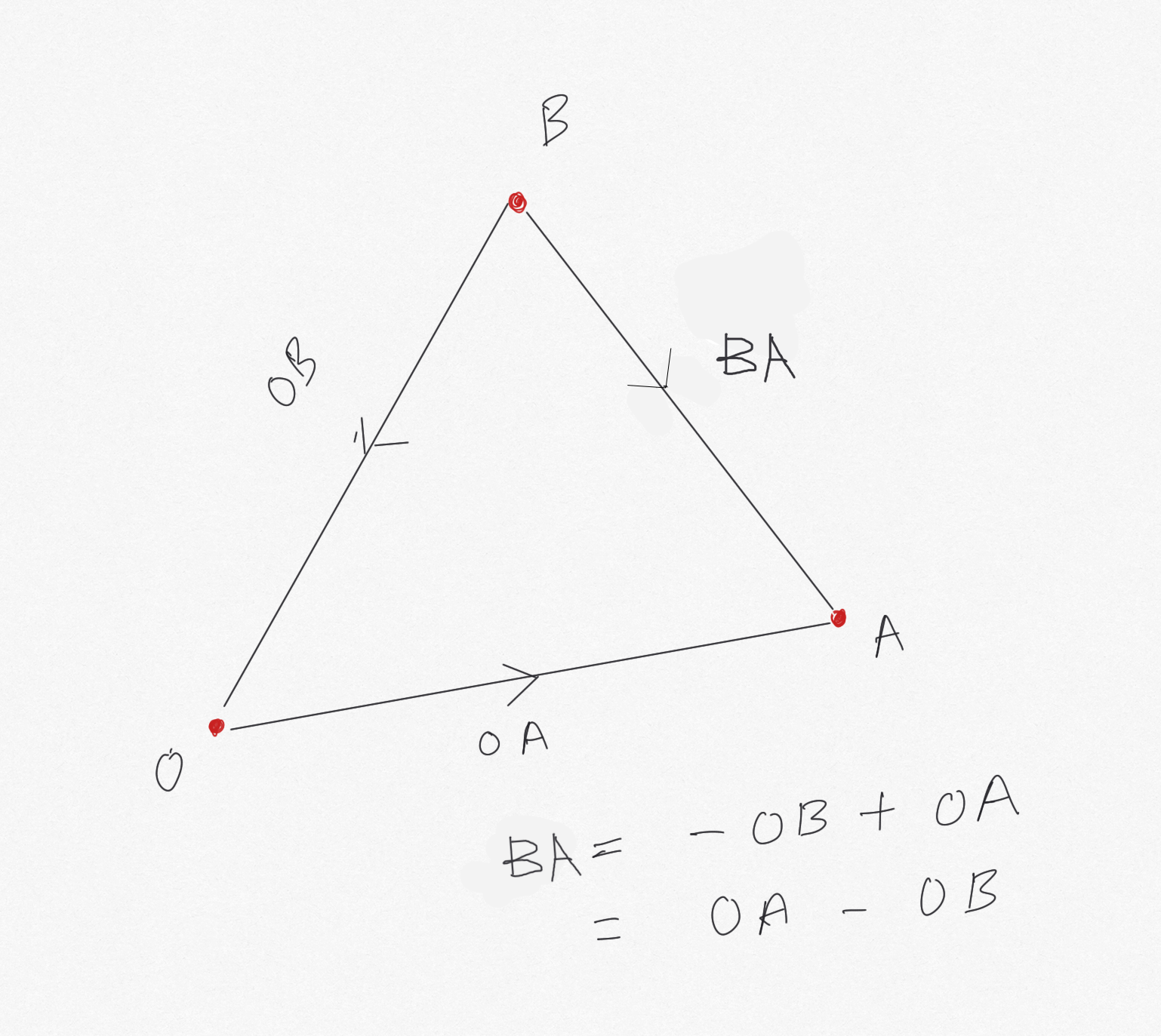
The vector from B to A (AB) is constructed as follows: come back from B to the origin -(b1, b2, b3), then go from the origin to A +(a1, a2, a3), i.e. (a1 - b1, a2 - b2, a3 - b3)
Using Pythagoras again, the distance from B to A is dBA:
dBA = square root ((a1 - b1)2 + (a2 - b2)2 + (a3 - b3)2)
Changing the origin
In AR, the origin O (0,0,0) changes as the camera position changes to O', representing the movement of the device.
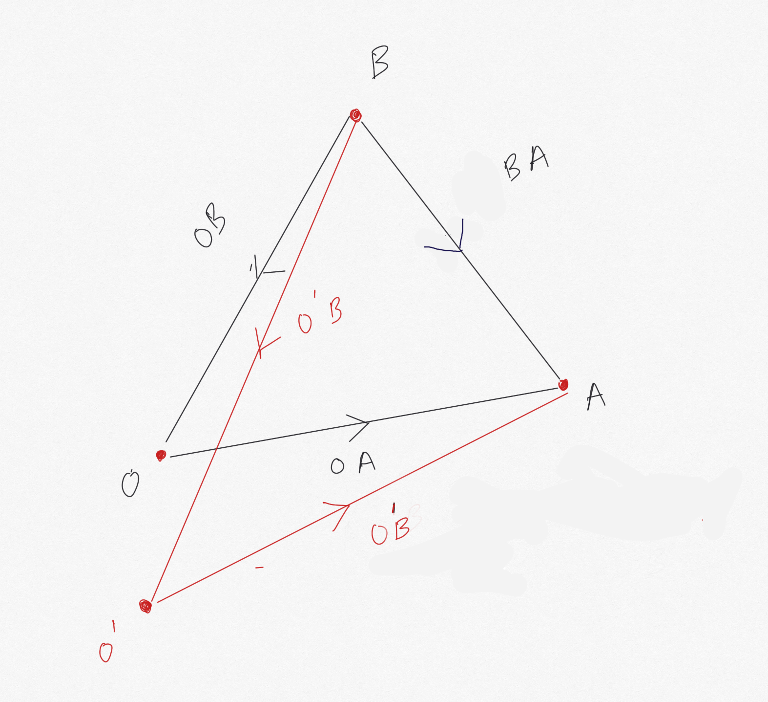
A and B have new vectors with respect to O': (a'1, a'2, a'3) and (b'1, b'2, b'3) respectively
Clearly, the lengths dA (with respect to O') of O'A and dB (with respect to O') of O'B change (because O' is in a different position to O), but the lenghth dAB doesn't change:
- OA = (a1, a2, a3), O'A = (a'1, a'2, a'3)
- OB = (b1, b2, b3), O'B = (b'1, b'2, b'3)
- dBA(with respect to O)
=
square root ((a1 - b1)2 + (a2 - b2)2 + (a3 - b3)2) - dBA(with respect to O')
=
square root ((a'1 - b'1)2 + (a'2 - b'2)2 + (a'3 - b'3)2) - dBA (with respect to O) = dAB (with respect to O')
- square root ((a1 - b1)2 + (a2 - b2)2 + (a3 - b3)2)
=
square root ((a'1 - b'1)2 + (a'2 - b'2)2 + (a'3 - b'3)2) - Squaring both sides:
(a1 - b1)2 + (a2 - b2)2 + (a3 - b3)2
=
(a'1 - b'1)2 + (a'2 - b'2)2 + (a'3 - b'3)2 - Similarly, a'1 - b'1 = a1 - b1, a'2 - b'2 = a2 - b2 and a'3 - b'3 = a3 - b3
By a similar, but much more complex diagram, we can understand that the angle between A and B with respect to each origin is the same. Intuitively, it doesn't matter what angle a camera is to A and B, the rotation (angle) someone at A needs to turn through to see B, doesn't change!
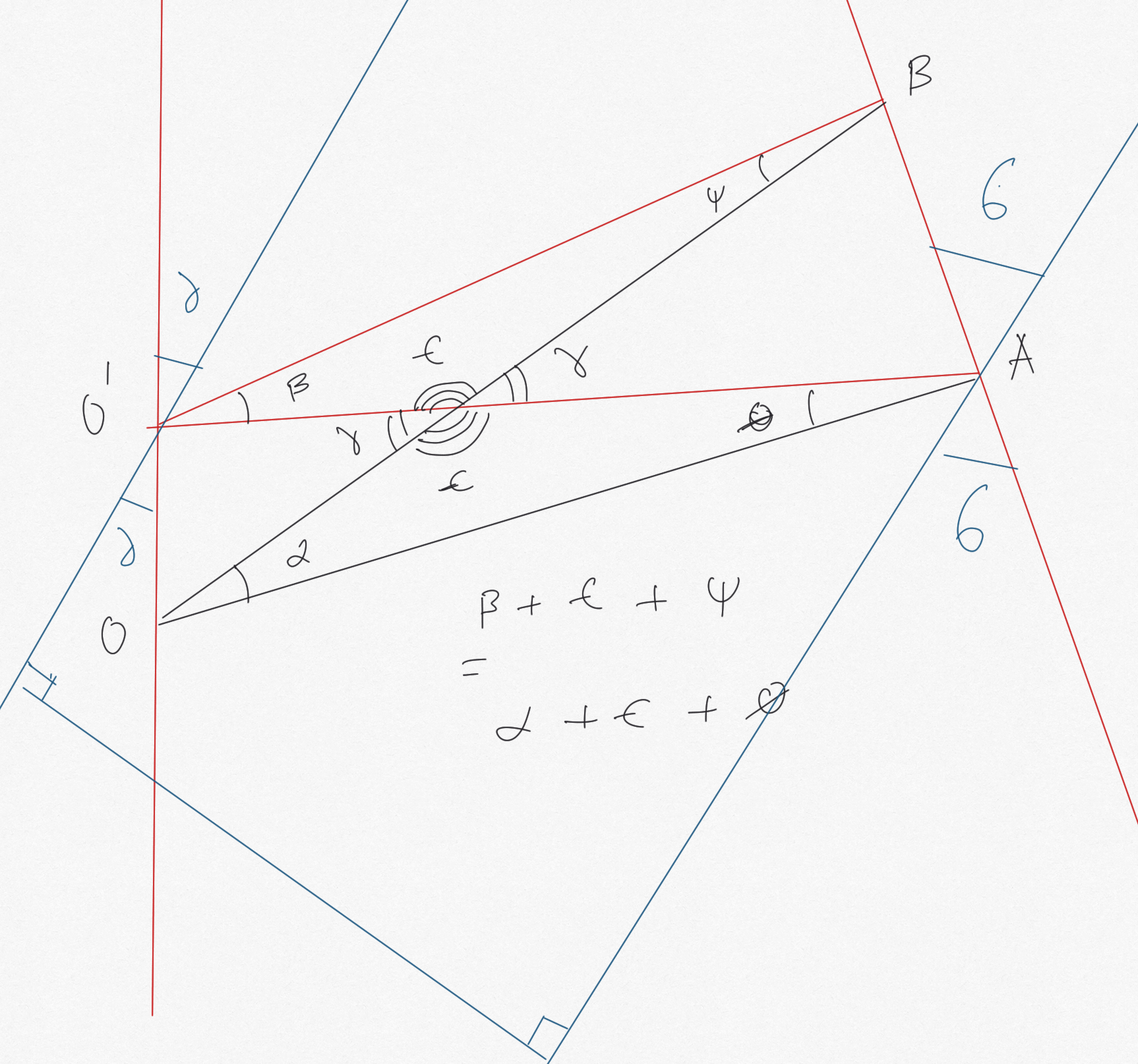
between things don't change no matter who's looking
However, the perceived distance and orientation between the objects (i.e. length and angle between them projected on the viewport) will change, so therefore we need to factor in the difference between angle and distance of OA and O'A to place new objects in the scene. This is why we need at least one marker in view at all times. The maths here is going to get tricky!
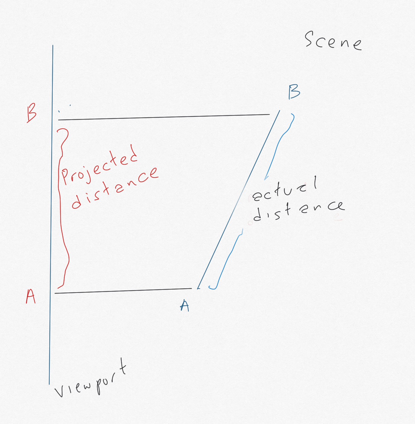
and perceived/projected distance between A and B
The point of this digression
The idea is that the distance and angle to two objects from different origins (camera positions) in an AR scene will change, but the distance and angle (rotation) between the two objects does not change. However, the distances and angles between objects do change when projected on the viewport. We want to simplify the mathematics of this projection to the extent it can create our reference polygon simply and quickly.
If the two objects are markers, we can proceed as follows:
- When two markers are in view, measure the distance and angle between them; record these
- When the camera moves, so that one marker goes out of view, reconstruct the out of view marker's position (now off-screen) using the previously recorded position and angle, given the new position of the in-view marker relative to the new origin
- Use the new distance and angle between the marker in view, with the recorded distance and angle from the marker in view to the marker out of view, to calculate the position of the marker out of view
- Use these positions to persist the orientation and position of objects relative to the positions of the markers, when at least one is in view
- In simpler terms, if we recorded where marker B was relative to marker A when they were both in view, that won't change, even if marker B is out of view, and nor will the positions and orientations of objects relative to A and B, irrespective of the change in camera position from O to O', whilst factoring in how the viewport has changed
- For example, the distance from the camera has changed by x, therefore we need to scale down the distance between A and B by a function of x
- As noted above, we will still need a marker in view, because we need that to anchor our new A and B positions relative to the new origin, as projected on the shifted viewport. For an extreme example, consider moving around enough so one marker is behind the camera, and the angle between the markers is now perpendicular to the viewport (!).
Experimenting with this idea
Two markers, constructing a a new line from one
Two markers showing two objects - using separate barcode markers Barcode 1 and Barcode 2 - distances and orientations shown when markers are in viewThe blue line is positioned using the recorded position and orientation of the red cube when the cube is viewed, and persists when the cube is out of view.
Note that, in this experiment, the length of the blue line does not change with the distance of the camera from the markers. This demonstrates our point about perceived distances when projected on the viewport.
Three markers, connected by a triangle
Three markers and a triangle - using separate barcode markers Barcode 1 and Barcode 2 and the Hiro marker
In this experiment, we construct a triangle connecting the three markers. If you click/touch anywhere, the nearest object will flash green. Proximity to the camera is indicated by the brightness of the object; the further away, the darker the object appears.
Notes
Note 1: Some maths required to get the length and orientation of the blue line to be relative to the green sphere. The idea here is to adjust the length to the distance between the sphere and cube, and the orientation to the angle between them.
Note 2: 'flickering' of the objects placed on markers is creating a lot of recalculations that get out of sync quickly - do we need to sample positions at set intervals so that the objects persist without themselves flickering? Is this an issue with older devices? Or is this a problem with oversampling?
Note 3: The blue line persists in relation to the camera when the object it is relative to goes out of shot. It 'sticks' to the view. This is kind of the point - when one marker goes out of view, we need to switch to a marker that is in view, and use that to anchor the blue line
Note 4: To a certain extent, you could say we are reinventing the wheel in the way we are creating projections of 3D objects on the viewport (there's lots of linear algebra we could do, for example). However, our aim here is to use the absolute minimum of calculation in order to place a persistent object within an AR scene - using simplified geometry and straightforward functions in order to approximate our result to an acceptable resolution. We don't need to be incredibly precise, or entirely correct, in our AR experience, we need to be plausibly accurate. And, more to the point, we need to work within the limitations of browser-based AR.